
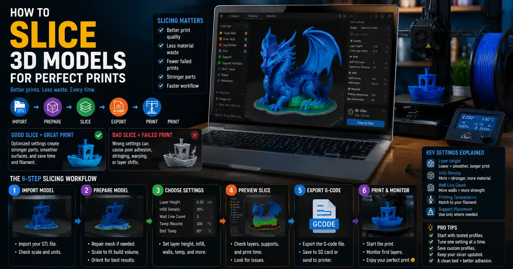
3D printing has transformed from a niche industrial tool to a accessible hobby and professional resource, letting makers turn digital designs into physical objects. But even the most well-designed digital model can end up as a failed print if you skip one critical step: proper 3D model slicing. Slicing acts as the bridge between your digital 3D model and your 3D printer, converting a 3D mesh into a step-by-step set of instructions that tells your printer exactly where to move, how much material to extrude, and what temperature to maintain. Whether you’re a beginner printing your first benchy or an experienced professional working on production parts, mastering how to slice 3D models will drastically improve your print quality, reduce material waste, and cut down on failed prints. This guide breaks down the entire process, from pre-slicing model prep to advanced tuning tips that work for every consumer 3D printer.
What Is 3D Slicing and Why Does It Matter?
At its core, 3D slicing is the process of cutting a digital 3D model into hundreds or thousands of thin, horizontal layers. For Fused Deposition Modeling (FDM) printers—the most common type of consumer 3D printer—each layer corresponds to a single pass of the extruder. For resin (MSLA/DLP) printers, slicing converts the 3D model into a series of 2D images that expose the resin layer by layer. In both cases, the sliced output is G-code (for FDM) or a sliced file (for resin) that your printer can read and execute.
Many new makers underestimate how much slicing settings impact final print quality. A perfectly designed model can come out lumpy, warped, or detached from the build plate if your slicer settings are wrong. Conversely, a slightly imperfect model can turn into a high-quality print with the right slicing adjustments. Slicing also lets you optimize prints for your specific needs: you can prioritize strength, speed, material savings, or surface finish depending on what the part will be used for.
There are dozens of slicer software options available today, ranging from free open-source tools to paid professional packages. Most beginners start with free options like Cura, PrusaSlicer, or Bambu Studio, which come pre-configured for popular printer models and offer enough customization for most use cases. Advanced users often turn to paid tools like Simplify3D or IceSL for more granular control over complex prints. No matter what tool you use, the core principles of effective slicing remain the same.
“Slicing is 90% of the battle in 3D printing. You can buy a $10,000 printer and the best filament on the market, but if your slicer settings are wrong, you’ll never get a good part.”
— Chad Jackson, 3D printing industry analyst and co-founder of 3D Print Action
Pre-Slicing: Prepping Your 3D Model for Success
Before you even open your slicer, your 3D model needs to be ready to slice. Skipping pre-slicing prep is one of the most common causes of slicing errors and failed prints. A corrupted or poorly exported mesh can cause your slicer to crash, create gaps in layers, or generate incorrect G-code that leads to extruder jams or misprints.
Check for Common Mesh ErrorsMost 3D models are shared as STL files, the standard format for 3D printing. STLs work by defining the surface of a model as a mesh of connected triangles, but it’s common for these meshes to have errors like non-manifold edges, overlapping triangles, holes, or flipped normals. These errors confuse slicers, which rely on a clean, closed mesh to correctly identify where the solid part of the model is and where the empty space is.
Fortunately, fixing most mesh errors is quick and free. Tools like MeshLab, Meshmixer, or even the built-in repair tool in most modern slicers can automatically fix 90% of common errors. For complex models, you may need to manually fill large holes or separate intersecting parts, but for most standard models, an automatic repair is enough.
Scale and Orient Your Model for Your PrinterOnce your mesh is clean, the next step is to scale your model to the correct size and orient it on the build plate. Scaling seems simple, but it’s easy to mix up units: many 3D models are designed in millimeters, but some are exported in inches, so double-check the bounding box dimensions against your printer’s maximum build volume before slicing.
Orientation is one of the most impactful choices you’ll make before slicing, and it depends on your priorities for the part:
- Surface finish: Place flat, visible faces parallel to the build plate to avoid visible layer lines on the most visible surfaces.
- Strength: Orient parts so that the highest stress loads run parallel to the layers, rather than perpendicular, to avoid layer separation under force.
- Supports: Orient the model to minimize overhangs greater than 45 degrees, which reduces the amount of support material you need and leaves a cleaner surface after support removal.
- Print time: Fewer overhangs and shorter height means faster print times, so orienting to minimize vertical height will speed up your print.
For example, if you’re 3D printing a custom phone case, you’d orient it flat with the back of the case against the build plate. This gives you a smooth front face with minimal supports, and maximizes strength for daily use. If you’re printing a tall, thin wrench, you’d orient it so the load-bearing jaw runs parallel to the layers to prevent it from breaking when you use it.
Hollowing and Lightening for Large PrintsFor large, bulky parts, you can save time and material by hollowing out the model before slicing. Most 3D modeling tools and meshing programs let you hollow a solid model and add a small drain hole (for resin prints, to let excess resin drain out) before exporting the STL. This step cuts down on material use significantly for large parts and can reduce internal stresses that cause warping in FDM prints. Just make sure you leave enough wall thickness to maintain the strength you need for your part—most of the time, 2-3mm of wall thickness is enough for non-load-bearing parts.
Core Slicer Settings Every User Should Master
Once your model is prepped and loaded into your slicer, it’s time to adjust the core settings that will define your print. Modern slicers come with pre-configured profiles for most popular printers and materials, which are a great starting point. But understanding what each setting does lets you tweak your prints to match your exact needs, rather than relying on generic profiles. Below are the core settings that have the biggest impact on print quality and success.
Layer HeightLayer height is the thickness of each individual horizontal layer that the printer will extrude. It’s one of the most impactful settings for both print quality and print time. Typical layer heights range from 0.08mm (very fine, high quality) to 0.3mm (coarse, fast print).
As a general rule, a thinner layer height gives you a smoother surface finish with less visible layer lines, but it increases print time because you need more layers to complete the same part. A thicker layer height is faster and can actually be stronger, because each layer bonds more thoroughly with a larger extruded bead. For functional parts that won’t be on display, a 0.2mm layer height is a good middle ground that balances speed and quality. for cosplay props or display pieces, 0.12mm or 0.16mm will give you a much smoother finish that requires less post-processing sanding.
Wall Thickness and Line WidthWall thickness defines how thick the outer solid walls of your print will be. It’s almost always calculated as a multiple of your nozzle’s line width, which is the width of the bead of filament your extruder puts down. For a standard 0.4mm nozzle, a common line width is 0.4mm, so most users use 2 or 3 walls for a total wall thickness of 0.8mm or 1.2mm.
Your wall thickness directly impacts the strength of your part: more walls mean a stronger, sturdier part, but also more material use and longer print times. For non-functional display parts, 2 walls (0.8mm for a 0.4mm nozzle) is enough. For functional parts that will see stress or use, 3 or 4 walls will give you much better durability. One common mistake new makers make is setting wall thickness that isn’t a multiple of line width, which leaves gaps in the walls. Most modern slicers automatically adjust this for you, but it’s good to double-check if you notice holes in your finished prints.
Infill Density and PatternInfill is the internal lattice structure that fills the inside of your hollow print. Infill settings have a huge impact on part strength, weight, material use, and print time. Infill density is the percentage of the internal volume that’s filled with material: 0% means the part is completely hollow (only walls), and 100% means the part is completely solid.
Most prints don’t need 100% infill. For most use cases, the sweet spot is:
- 0-10%: Display parts, cosplay props, or decorative items that don’t carry any load
- 10-25%: General use parts, toys, or prototypes that need minor rigidity
- 25-50%: Functional parts that will carry moderate loads, like brackets, tool handles, or kitchen accessories
- 50-100%: High-stress industrial parts, mechanical components, or parts that need to be water or air tight
Infill pattern also matters: common patterns include grid, gyroid, triangles, and hexagonal. Gyroid infill is the most popular for modern prints because it offers excellent strength-to-weight ratio, is faster to print than more complex patterns, and distributes stress evenly across the part. Grid infill is simple and fast, but weaker along one axis, while triangular infill is very strong but slower to print.
Temperature and SpeedNozzle and bed temperature are entirely dependent on the material you’re using. PLA, the most common beginner filament, typically prints at 190-210°C with a bed temperature of 50-60°C. PETG prints at 220-240°C with a bed temperature of 70-80°C, and ABS prints at 230-250°C with a bed temperature of 100-110°C. Always check the manufacturer’s recommendation for your specific filament, as different blends can have slightly different requirements.
Print speed is a balancing act between print time and quality. Most consumer FDM printers can print reliably at 50-100mm per second for outer walls, and 100-150mm per second for infill. Faster speeds can cause vibrations that lead to ringing (ghosting) on fine details, so if you’re printing a part with sharp details, slow down the outer wall speed to 30-50mm per second for cleaner results.
Support and Build Plate AdhesionSupports are extra structures that the slicer adds to hold up overhangs (sections of the model that stick out with nothing under them). Most FDM printers can handle overhangs of 45 degrees or steeper without support, so your slicer’s default “generate support for overhangs over 45 degrees” setting works for most cases. For complex models with lots of overhangs, you can use “tree supports” which use less material and leave a cleaner surface than normal supports, and only touch the model at small contact points.
Build plate adhesion settings help prevent your print from warping or detaching from the build plate mid-print. The most common options are:
- Brim: A thin, flat extension of the first layer around the base of your print. It adds extra surface area to hold the print down and is great for small or tall prints with small bases.
- Raft: A thick, lattice base that the entire print sits on top of. It’s useful for very warping-prone materials like ABS or for models with very little base contact, but it adds material and post-processing work to remove.
- Skirt: A thin outline around the base of the print that doesn’t touch the model. It primes the extruder before it starts printing the model, ensuring filament is flowing evenly, but doesn’t help with adhesion.
For most PLA prints on a textured build plate, a brim or skirt is all you need. For larger prints or more warping-prone materials, a raft may be necessary to get a successful print.
Step-by-Step Slicing Workflow for FDM 3D Printing
Now that we’ve covered the core concepts, let’s walk through a practical, step-by-step workflow for slicing a 3D model for FDM printing, using the free popular slicer Ultimaker Cura as an example. This workflow works for any slicer, just adjust the menu names to match your software.
Import and prepare your model: Open your slicer, import your pre-repaired STL file, and drag it to position it on the build plate. Use the scaling tool to adjust the size to your desired dimensions, and rotate the model to your chosen orientation. Double-check that the entire model fits within your printer’s build volume (the bounding box will turn red if it’s too big).
Select your printer, material, and quality profile: Choose your specific 3D printer model from the printer dropdown, then select your material (PLA, PETG, etc.) and your desired quality (fine, standard, draft). This will load a pre-configured base profile that sets all core settings for your setup, which is a great starting point for beginners.
Adjust core settings for your use case: Tweak the core settings we covered earlier to match your part’s purpose. If you’re printing a functional wrench, increase wall thickness to 1.2mm and infill density to 40%. If you’re printing a display statue, drop layer height to 0.12mm and set infill to 10% to save material.
Configure supports and adhesion: Enable support for overhangs over 45 degrees, and turn on tree supports if your slicer has them to save material. Choose your adhesion type: brim for small prints, skirt for large prints with a wide base, raft for warping-prone materials. Use the “paint on supports” tool if you need to add supports to specific areas or remove supports from areas where you don’t want them, like a hole that will be cleaned up post-print.
Preview the sliced model: Before exporting G-code, use the slicer’s preview tool to look at every layer of the sliced model. Check for gaps in walls, missing layers, or unexpected support placements. Look for areas where the extruder will travel over open space without extruding, which can cause oozing on the surface of your print. Most slicers will also flag common errors like unprintable overhangs or out-of-bounds models at this stage.
Export and transfer G-code: Once you’re happy with the preview, export the G-code file to an SD card or transfer it directly to your printer via Wi-Fi if your printer supports it. Make sure the file is saved in a format your printer can read—most FDM printers use raw .gcode files, but some proprietary systems use different formats.
For resin 3D printing, the workflow is very similar, with a few key differences: you’ll need to add drain holes to hollowed models before importing, enable hollowing in your slicer if you didn’t do it in pre-processing, and adjust layer height based on your resin printer’s layer capability (most resin printers can go as low as 0.02mm for extremely high detail). The output for resin slicing is a sliced .ctb or .photon file instead of G-code, but the core principles of model prep, orientation, and setting adjustments remain the same.
Advanced Slicing Tips for Better Print Quality
Once you’ve mastered the basic workflow, there are a few advanced tweaks you can use to get even better results from your prints. These small adjustments can fix common problems like stringing, ringing, and poor layer adhesion, and help you get the most out of your 3D printer.
Enable Retraction to Reduce StringingStringing—those thin strands of filament that are left behind when the extruder travels across open gaps between parts—can ruin the surface finish of a print. Retraction is a setting that pulls filament back slightly when the extruder is moving, so it doesn’t ooze out as it travels. For most printers, a retraction distance of 2-5mm for Bowden extruders and 0.5-2mm for direct drive extruders, combined with a retraction speed of 20-50mm per second, will eliminate most stringing. You can also enable “coasting” which stops extruding a little before the end of a wall to eliminate blobs at the start/end of each layer.
Use Adaptive Layer Height for Fine DetailsAdaptive layer height is a feature that automatically changes the layer height based on the slope of the model. It uses a thinner layer height for steep slopes and fine details, and a thicker layer height for flat areas, so you get the best of both: high quality on detailed areas and faster print times for the rest of the model. This is a great feature for miniatures, figurines, or models with lots of intricate details, and it can cut print time by 20-30% compared to slicing the entire model at a fine layer height.
Optimize for Strength with Gyroid Infill and PerimtersIf you’re printing functional parts that need to be strong, you can optimize your slicing settings to maximize strength without adding too much extra material. Use gyroid infill instead of grid or triangular infill for a better strength-to-weight ratio, and enable “ironing” on top solid layers to get a perfectly smooth top surface that doesn’t have gaps between lines. You can also add extra perimeters (walls) around holes to increase their strength and reduce wear if you’re using screws or bolts in the part.
Use Print Speed Variation to Reduce RingingRinging, also called ghosting, is the pattern of faint ripples that appear on flat surfaces near sharp details, caused by the printer’s nozzle vibrating when it changes direction quickly. Most modern slicers let you slow down the print speed for small perimeters and small details, which reduces vibration and eliminates most ringing. You can also enable vibration compensation if your printer and slicer support it, which further reduces ringing by compensating for the printer’s natural resonance.
Conclusion
Learning how to slice 3D models correctly is the most important skill you can develop as a 3D printing maker. It doesn’t require expensive software or advanced engineering knowledge—just an understanding of core settings, a consistent pre-slicing workflow, and a willingness to tweak settings based on your results. Start with pre-configured profiles from your slicer or printer manufacturer, then adjust one setting at a time to see how it impacts your prints. Over time, you’ll build an intuition for what settings work for different types of parts and materials, and you’ll be able to consistently get high quality, successful prints.
Remember that there’s no one “perfect” set of slicing settings that works for every print. The right settings depend on what you’re printing, what material you’re using, what your printer is capable of, and what you prioritize for the final part. Whether you prioritize speed for rapid prototyping, strength for functional parts, or smooth finish for display pieces, mastering slicing lets you tailor every print to your exact needs. With the steps and tips outlined in this guide, you’re ready to start slicing better and printing more successfully, no matter what 3D printer you own.