
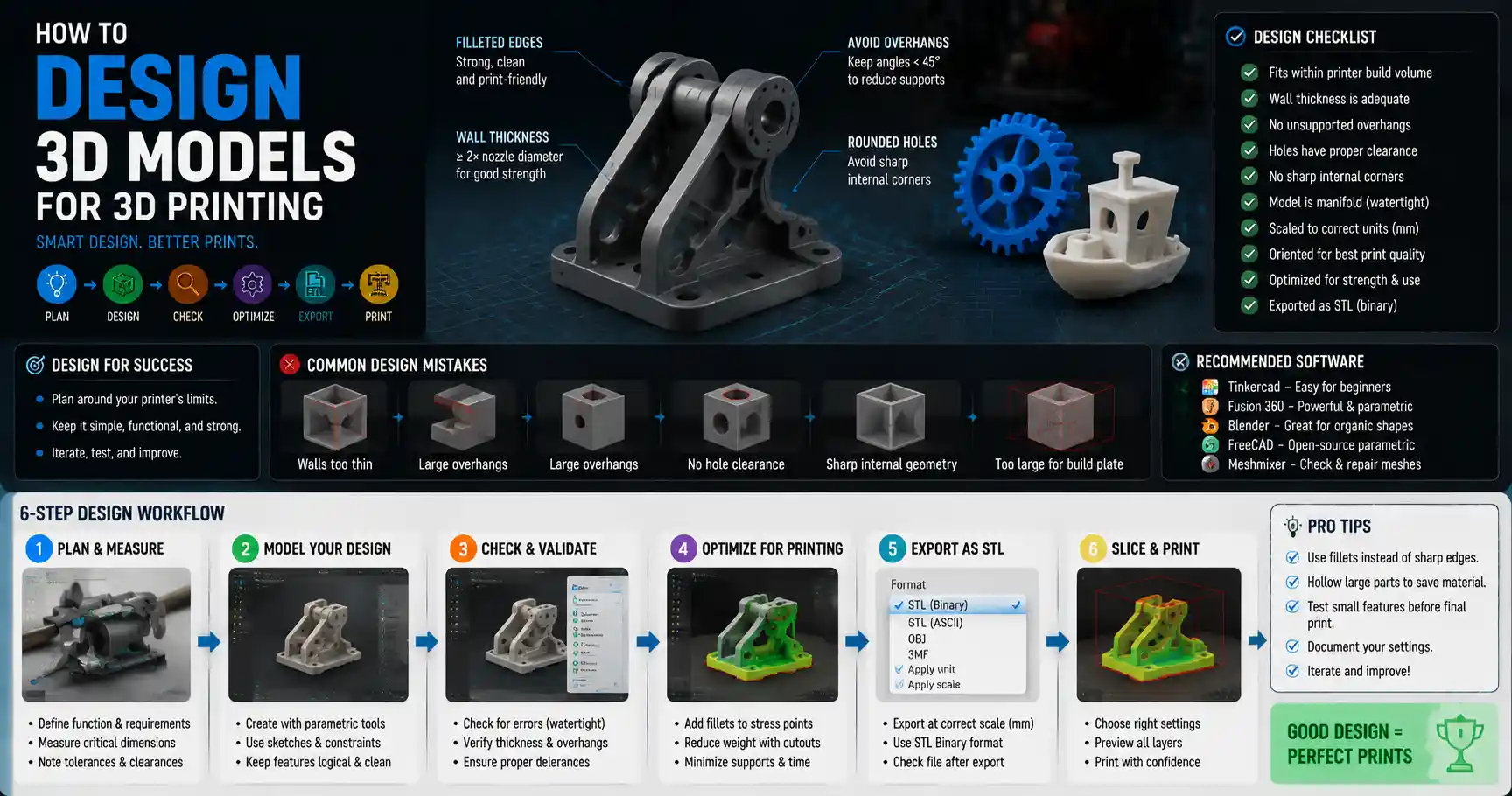
3D printing has transformed from a niche industrial tool into an accessible hobby and professional workflow, with millions of home printers now operating across North America, Europe, and Oceania. While pre-made models from sites like Thingiverse and MyMiniFactory are great for beginners, many makers eventually want to design their own custom prints – whether that’s a replacement part for a broken kitchen appliance, a personalized gift for a friend, or a prototype for a new product idea. Designing a model that actually prints successfully, without layer separation, warping, or failed supports, takes more than just dragging shapes in a 3D modeling program. This guide breaks down the entire process, from initial planning to final export, to help you create 3D printable models that work on the first try.
Start with Planning: Align Your Design with Your Printer’s Capabilities
Many new designers jump straight into CAD (computer-aided design) software without considering the limitations of their 3D printer, leading to frustrating failed prints before they even export the file. Taking 15 minutes to plan your design around your hardware will save hours of rework later. Even professional industrial designers start with this step, because every printer has unique constraints that affect what you can and cannot create.
Measure Twice, Design Once: Define Size and Function First
Before you open any modeling software, write down the core purpose of your model and its critical dimensions. If you’re designing a phone stand, you need to know the exact dimensions of your phone, the thickness of your case, and how much clearance you need for a charging cable. If you’re designing a replacement bracket for a shelf, measure the existing screw holes and the space it needs to fit with a digital caliper – eyeballing measurements almost always leads to ill-fitting prints.
It’s also important to distinguish between critical dimensions and non-critical dimensions. Critical dimensions are measurements that directly affect how the model fits or functions – for example, the diameter of a hole that needs to fit around a 10mm bolt. Non-critical dimensions are cosmetic: the curve of a handle, the size of a decorative logo. Prioritize getting critical dimensions perfect, and allow for small variations in cosmetic features to simplify your design.
Match Design Complexity to Your Printer
Every 3D printer has a minimum feature size, maximum build volume, and different capabilities when it comes to overhangs and supports. Fused Deposition Modeling (FDM) printers, the most common type for home use, can’t print features smaller than around 0.3mm (12 thou) reliably, because the nozzle diameter itself is usually 0.4mm. Resin printers, which use UV-cured liquid resin, can print much finer details as small as 0.1mm, making them better for miniatures, jewelry, and high-detail prototypes.
Common printer constraints you should note before designing include:
- Build volume: the maximum X, Y, and Z dimensions your printer can produce. If your design is larger than your build volume, you’ll need to plan to split it into multiple interlocking parts from the start.
- Nozzle diameter: smaller nozzles (0.2mm) can print finer details, while larger nozzles (0.6mm) print faster but can’t produce small features. Adjust your minimum wall thickness to match your nozzle – a good rule of thumb is minimum wall thickness equal to twice your nozzle diameter.
- Support requirements: most FDM printers can only print overhangs steeper than 45 degrees without supports, while resin printers can handle much shallower angles. If you don’t want to use supports (which leave rough marks on your print and increase material use), plan your design to avoid overhangs steeper than this limit.
Choose the Right 3D Modeling Software for Your Skill Level and Use Case
There are dozens of 3D modeling programs on the market today, ranging from free open-source options to thousand-dollar professional suites. Choosing the right tool for your needs will speed up your design process and reduce frustration. The best software for you depends on what you’re designing, how much experience you have, and what your budget is.
Beginner-Friendly Free Options
If you’re new to 3D design, you don’t need to invest in expensive software to get started. Free options like Tinkercad, a browser-based tool from Autodesk, are perfect for learning the basics of 3D modeling. Tinkercad uses a simple “click and drag” workflow based on primitive shapes (cubes, cylinders, spheres) that you combine or subtract to create your model. It’s ideal for functional prints like replacement parts, phone stands, and storage organizers, and it exports directly to STL, the standard file format for 3D printing.
Blender, another free open-source program, is a better choice if you want to design organic, curved models like figurines, art pieces, or custom action figures. Blender has a steeper learning curve than Tinkercad, but there are thousands of free tutorials available on YouTube for 3D printing-specific design. For intermediate beginners looking to move past primitive shapes, FreeCAD is a popular open-source parametric CAD tool that lets you adjust dimensions easily after you’ve started designing, which is perfect for iterating on functional parts.
Professional and Paid Options
If you’re designing parts for professional prototyping or need advanced parametric functionality, paid tools like Fusion 360, SolidWorks, and Rhino are industry standards. Autodesk Fusion 360 is the most popular choice for small businesses and independent makers, because it offers a low-cost subscription ($60 per year for hobbyists) and combines parametric modeling, mesh editing, and even CAM toolpaths for CNC machining in one program. It also has built-in tools to check your model for 3D printing errors before export, which is a huge time-saver.
“The biggest mistake new designers make is choosing a software that’s too advanced for their current skill level. You don’t need SolidWorks to design a keychain; start with Tinkercad, master the fundamentals of watertight geometry, and work your way up.”
Regardless of what software you choose, make sure it can export your model as an STL or OBJ file – these are the two file formats that all 3D printing slicers accept. Some advanced programs export in STEP or IGES formats, which are great for manufacturing but need to be converted to STL before 3D printing.
Core Design Principles for 3D Printability
Once you’ve planned your design and chosen your software, it’s time to start building your model. There are a few universal design rules that apply to all 3D printing technologies, whether you’re using FDM, resin, or industrial SLS. Following these rules will drastically reduce your rate of failed prints and produce higher quality finished parts.
Ensure Watertight, Manifold Geometry
The most common issue with 3D printable models is non-manifold geometry – that is, geometry that has holes, overlapping faces, or disconnected edges that confuse the slicer software. When your model isn’t watertight, the slicer can’t tell the difference between the inside and outside of the model, which leads to missing layers, incomplete prints, or crashed slicer processes.
To avoid non-manifold geometry, follow these simple rules when modeling:
- Always close all open edges: every outer face of your model should connect to another face with no gaps. If you’re cutting a hole in a block, make sure the hole goes all the way through or that the back of the hole is capped with a face.
- Avoid overlapping or duplicate faces: two faces occupying the same space confuse slicers, so always delete overlapping geometry after you’ve combined or subtracted shapes.
- Join all disconnected parts: if your design has multiple separate pieces in one STL file, make sure they are all merged into a single solid object in your CAD software before export.
Most modern CAD programs have built-in analysis tools to check for non-manifold geometry, so run a check before you export your file. If you do find errors, many tools can automatically fix small issues for you.
Design for Wall Thickness and Strength
Walls that are too thin will print poorly, crack easily, or even fail to print at all on FDM printers. As a general rule, the minimum wall thickness for FDM printing is 1.2mm (for a 0.4mm nozzle), which gives you three solid perimeters. For functional parts that need to hold weight, increase this to 2mm or more. For resin printing, you can go as thin as 0.5mm for decorative parts, but 1mm is a safer minimum for functional pieces.
When designing walls, it’s also important to match your wall thickness to a multiple of your nozzle diameter. For example, a 0.4mm nozzle will produce clean, solid walls at 1.2mm (3 x 0.4mm) or 1.6mm (4 x 0.4mm), because the slicer can fit complete perimeter lines without needing to fill in gaps with partial-width extrusions. Partial extrusions often lead to blobby, inconsistent walls.
For large, hollow parts, you don’t need to make the entire part solid – that wastes material and increases print time. Instead, use thick outer walls and an internal infill pattern to add strength without extra weight. Most slicers will automatically generate infill based on your settings, but you can design internal reinforcement ribs into your model for extra strength in high-stress areas.
Handle Overhangs and Bridges Correctly
Overhangs are any part of the model that extends out horizontally from the layer below it. As we mentioned earlier, most FDM printers can only print overhangs up to 45 degrees from vertical without supports. If your design has an overhang steeper than 45 degrees, you have two options: add a Chamfer to the overhang to reduce the angle, or design it in a way that eliminates the overhang entirely.
A common trick for designing overhangs is to add fillets to sharp internal corners instead of leaving them 90 degrees. A 90-degree internal corner requires a 90-degree overhang for the top part of the corner, which will always need supports. A rounded fillet gradually increases the angle of the overhang, often bringing it within the 45-degree limit and eliminating the need for supports.
Bridges are horizontal spans between two vertical supports, like the top of a box. Most printers can print bridges up to a few centimeters long without supports, but bridges longer than 5cm will sag in the middle without support. To improve bridge quality, you can add a slight downward curve to the bridge in your design – when it sags during printing, it will straighten out to the correct flat shape.
Design Interlocking Parts and Tolerances
If you’re designing a model with multiple moving or fitting parts – like a hinge, a snap-fit box, or a screw – you need to add tolerance to your design. Tolerance is the intentional gap between two parts that accounts for the slight over-extrusion that happens in all 3D printing. If you design a 10mm hole to fit a 10mm rod, the hole will end up slightly smaller than 10mm after printing, so the rod won’t fit.
The amount of tolerance you need depends on your printer and your layer height, but good starting points are:
- For FDM printers: add 0.2mm to 0.4mm of clearance between moving parts. For a 10mm diameter rod, make the hole 10.3mm to 10.4mm.
- For resin printers: add 0.1mm to 0.2mm of clearance, since resin printing produces much more accurate dimensions.
- For press fits or snap fits: reduce clearance by 0.1mm to 0.2mm to get a tight fit.
It’s always a good idea to print a small test fit of your tolerances before printing the entire large part. For example, if you’re designing a box with a snap-fit lid, print just one corner first to check that the snap fits work and the lid fits correctly, then adjust the tolerance if needed before printing the whole box. This saves a lot of time and material compared to reprinting the entire part.
Pre-Export Checks and STL Preparation
Once you’ve finished modeling your design, don’t just export the STL and send it to your slicer. A few quick checks and corrections will catch most common errors before you waste time printing. Even experienced designers miss small issues, so this step is non-negotiable.
Check for Errors in Your CAD Software
Start by running your CAD software’s built-in 3D print check or solid analysis tool. Most modern tools like Fusion 360, SolidWorks, and Tinkercad will automatically flag common issues like open edges, non-manifold geometry, and walls that are too thin. Fix any issues that the tool flags before moving on.
If you’re using a mesh-based modeling program like Blender, you can use the built-in 3D Print Toolbox add-on to check for errors. This tool will count the number of non-manifold edges, find isolated faces, and check for zero-area faces that can cause slicing errors.
Use Mesh Repair Tools if Needed
If your CAD software can’t fix an error, or you’re working with a downloaded mesh that you modified, you can use free online tools like MeshMixer or MakePrintable to automatically repair your STL. MeshMixer, which is made by Autodesk, is a free download that has a powerful “Make Solid” tool that can fill gaps, fix non-manifold geometry, and smooth out irregular faces. For simple repairs, you can even use online tools that let you upload your STL and fix it in a few clicks without downloading any software.
Be careful when using automatic mesh repair tools, however. Sometimes they can add extra material or change small critical dimensions, so always check the repaired mesh against your original design to make sure it didn’t accidentally change any critical features like hole diameters or mounting points.
Optimize for Slicing
Before you export your STL, adjust the resolution of your mesh to balance detail and file size. If your mesh has too many triangles, it will be slow to load and slice on older computers. If it has too few triangles, curved surfaces will come out looking blocky and faceted. A good rule of thumb is to set the STL export tolerance to 0.01mm, which gives enough detail for 3D printing without creating an unnecessarily large file.
If you’re printing a large model that needs to be split into multiple parts, most CAD programs and meshing tools have built-in splitting tools that let you cut the model into sections and add alignment pegs and holes to make it easy to glue together later. Designing alignment pegs from the start ensures that your parts fit together correctly after printing, instead of having to guess the alignment when gluing.
Test, Iterate, and Refine Your Design
Even if you’ve followed all the design rules, your first print will rarely be perfect. Iteration is a core part of 3D design, and the best designers use test prints to refine their models before creating the final version.
Start with a proof of concept print that only includes the critical parts of your design. For example, if you’re designing a custom drone frame, print just the motor mount and battery holder first to check that the dimensions and fit are correct, instead of printing the entire 10-hour frame. This lets you adjust tolerances, wall thickness, or overhang angles without wasting hours of print time and kilograms of filament.
After your test print, measure the finished part with your caliper to check how accurate your printer is. For example, if you designed a 10mm hole and it comes out at 9.7mm, you know you need to add 0.3mm to all hole diameters in your future designs for your specific printer. Every printer has slightly different tolerances based on its calibration, so keeping a note of your printer’s specific offset for different feature types will help you design more accurate models faster in the future.
If you’re sharing your models online, it’s also a good idea to note what printer and material you tested it on, and what tolerances you used. This helps other makers adjust the model for their own printers if needed, and reduces the number of comments from people who can’t get the parts to fit.
Conclusion
Designing 3D printable models is a skill that improves with practice, but following a structured process will help you avoid the most common mistakes that new designers make. Start by planning your design around your printer’s capabilities, choose a modeling tool that matches your skill level, and follow core design rules like watertight geometry, correct wall thickness, and proper tolerances. Always check your model for errors before exporting, and test the critical parts of your design before printing the full model. Over time, you’ll develop a feel for what works on your specific printer, and you’ll be able to design custom functional and decorative models that print perfectly on the first try. Whether you’re a hobbyist looking to make personalized projects or a professional prototyping a new product, these fundamentals will serve as a solid foundation for all your 3D design work.