
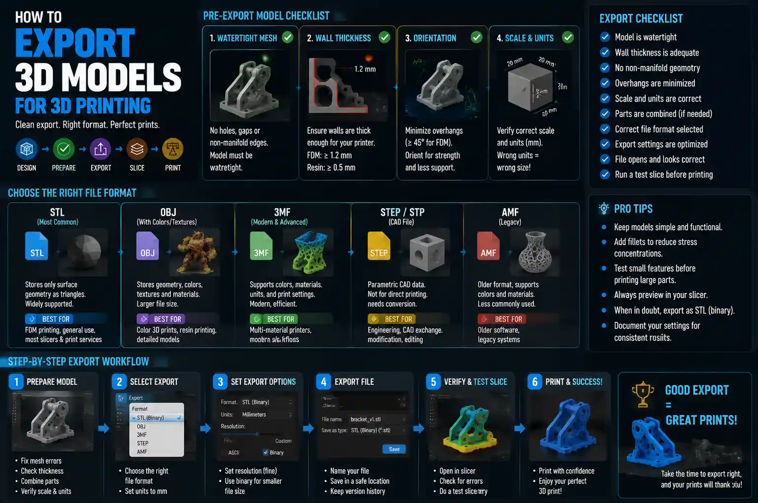
Whether you’re a product designer prototyping a new invention, a hobbyist printing custom cosplay armor, or an engineer iterating on a functional mechanical part, exporting a 3D model correctly is the most critical step between your digital design and a successful physical print. A beautiful, perfectly dimensioned model in your CAD or modeling software can turn into a warped, misprinted mess if you make even small mistakes during export. Learning how to export for 3D printing doesn’t require advanced engineering skills, but it does require attention to a few key details that many new designers overlook. In this guide, we’ll break down the entire process, from preparing your model in-software to choosing the right file format and troubleshooting common export errors.
Pre-Export Model Preparation: Fix Common Issues Before You Export
Before you even touch the export button, your 3D model needs to meet the basic requirements of 3D printing. Most consumer and industrial 3D printers rely on solid geometry, not just pretty surface meshes, so skipping pre-export checks is the number one cause of failed prints. Fixing issues in your modeling software is far easier than troubleshooting them in your slicer after export.
Ensure Your Model Is Watertight (No Holes or Non-Manifold Geometry)
The most important rule for 3D printable models is that they must be watertight: this means every edge connects to exactly two faces, with no gaps, holes, or overlapping surfaces that would leave the "inside" of the model undefined. Non-manifold geometry, the term for any mesh that breaks this rule, confuses slicers, which can’t tell where the solid part of your print ends and empty space begins. Common causes of non-manifold geometry include:
- Deleted faces that leave gaps in the mesh, often from importing files from other software
- Overlapping edges or faces where two parts of the model were merged incorrectly
- Three or more faces sharing a single edge, which creates ambiguous geometry
- Internal surfaces that don’t contribute to the outer shape of the model
Most modern CAD and modeling tools include built-in checks for non-manifold geometry. For example, Blender has a "3D Print Toolbox" add-on that automatically highlights errors, while Fusion 360 flags gaps in solid models during its mesh preview. If you’re working with a mesh model (rather than a CAD solid), tools like Meshmixer can automatically fill small holes and repair non-manifold edges with a single click. For solid CAD models, always use the union or combine tool to merge multiple separate parts into a single solid before export, which eliminates overlapping geometry automatically.
Check Wall Thickness and Printability
Another common pre-export mistake is designing walls that are too thin for your 3D printer’s nozzle. Most FDM 3D printers use a 0.4mm nozzle, so the minimum printable wall thickness is generally 1.2mm (three times the nozzle diameter) to ensure the nozzle can lay down consistent, solid walls. If you’re exporting for resin printing, you can go as thin as 0.5mm for fine details, but even resin printers have lower limits. Always check your printer’s specifications before finalizing your model, and adjust wall thickness in your design software before exporting.
A good rule of thumb: if a wall is thinner than the diameter of your printer’s nozzle, it won’t print at all, or it will be so fragile that it breaks off immediately. For functional parts that need strength, aim for 2-3mm wall thickness, which works for most FDM printers without requiring extra material.
Orient for Print Success (Optional but Recommended)
While most users orient their model in the slicer, some designers prefer to orient before export to ensure overhangs, layer lines, and strength are positioned correctly for the part’s purpose. For example, a functional lever that needs to withstand bending force should be oriented so layers run along the length of the lever, not across it, since layer adhesion is always the weakest point of a 3D print. If you’re exporting a single part that will be printed as-is, orienting it before export saves time later and ensures you don’t forget to adjust the orientation in the slicer.
Choosing the Right File Format for Your 3D Printing Workflow
Once your model is repaired and ready, the next step is choosing the right file format for your use case. Not all 3D file formats are created equal, and the right choice depends on whether you’re printing the model yourself, sharing it with someone else, or sending it to a professional 3D printing service. Below are the most common formats, and when to use each.
STL: The Industry Standard for Most Use Cases
Standard Tessellation Language (STL) has been the default 3D printing file format for decades, and it’s still the most widely supported by slicers, consumer printers, and print services. STL works by converting your solid model into a mesh of triangular facets that describe the outer surface of your part. It’s simple, lightweight, and compatible with every 3D printing software you’ll encounter.
The biggest downside of STL is that it stores only surface geometry, not dimensions or parametric data. That means if you need to edit the model later, you can’t easily change dimensions like you can with a CAD file. STL also relies on triangular facets, so the quality of your export depends on how finely you tessellate (divide) the surface. Too few facets, and you’ll get jagged, blocky curves; too many, and the file becomes unnecessarily large and slow to process in your slicer.
When to use STL: Almost all consumer 3D printing workflows, sharing models online, and sending files to most print services. If you’re printing at home, STL is almost always the right choice.
OBJ: For Full-Color and High-Detail Resin Printing
OBJ is another mesh-based format, but unlike STL, it stores texture and color information alongside geometry. That makes it the go-to choice for full-color 3D printing, like multi-material resin prints or powder-based full-color prints from services like Shapeways. OBJ also handles high-detail meshes more efficiently than STL in some cases, and it preserves texture mapping for models designed to show different colors or surface finishes.
For standard single-material FDM printing, OBJ offers no real benefit over STL, and some older slicers don’t support it natively. But if you’re working on a full-color project or a high-detail miniature for resin printing, OBJ is often the better choice.
3MF: The Modern Replacement for STL
Developed by the 3MF Consortium, which includes major companies like Microsoft, Autodesk, and Prusa Research, 3D Manufacturing Format (3MF) is designed to fix the limitations of STL. 3MF stores more than just surface mesh geometry: it can include multiple parts, color information, material assignments, print settings, and even metadata like part orientation, all in a single compressed file. It doesn’t rely on triangular facets the same way STL does, so it preserves higher quality curves without creating huge file sizes.
"STL was invented in 1987 for a very different 3D printing industry than we have today. 3MF brings the format into the modern age, eliminating dozens of common errors and adding features that multi-material and advanced printers need to work correctly."
Most modern slicers (including PrusaSlicer, Cura, and Bambu Studio) now support 3MF natively, and it’s quickly becoming the preferred format for home users. The only downside is that some older printers, print services, and online model platforms still don’t accept 3MF, so STL is still a safer bet for sharing in many cases. If you’re working with a modern workflow that supports it, though, 3MF is almost always the better choice.
STEP/IGES: For Professional CAD and Print Services
If you’re sending a part to a professional 3D printing service for industrial 3D printing (like CNC machining, SLS, or metal 3D printing), you’ll often be asked to provide a STEP (or IGES) file instead of a mesh format like STL. STEP files store full parametric solid CAD data, not just a surface mesh, which allows the print service to check your model for errors, adjust dimensions, and re-mesh it to their exact requirements. That eliminates the risk of a bad mesh export causing a failed print when you’re paying hundreds of dollars for a professional part.
For home 3D printing, STEP files are overkill, since slicers don’t process solid CAD data directly. But for professional projects, always keep a copy of your original STEP file, and provide it to your print service when requested.
Step-by-Step Export Settings for Common 3D Modeling Software
Every popular 3D modeling and CAD tool has its own export process, and getting the settings right makes a huge difference in the quality of your final file. Below, we’ve broken down step-by-step best practices for the most common tools used by hobbyists and professionals alike.
Exporting from Fusion 360
Fusion 360 is one of the most popular CAD tools for 3D printing, and it has robust export options for all common file formats. To export for 3D printing:
- First, use the "Combine" tool to merge all solid bodies into a single body if you’re exporting a single part. This eliminates overlapping geometry automatically.
- Go to File > Export, then select your desired file format (STL, 3MF, or STEP).
- For STL/3MF, adjust the "Refinement" setting. The default medium setting works for most parts, but if you have small, detailed curves, switch to high. Avoid extreme high refinement unless you need it, as it can create a 100MB+ file that slows down your slicer.
- Check the "Export selected bodies only" box if you only want to export specific parts of your design, then click export.
A pro tip for Fusion 360 users: Use the "Make" > "3D Print" tool instead of the general export function. This tool automatically checks for non-manifold geometry and gaps before export, and it lets you preview the mesh right in the software, so you can catch errors before you save the file.
Exporting from Blender
Blender is the go-to free tool for organic 3D models like miniatures, cosplay props, and art pieces, but it’s also the tool where new users make the most export mistakes. Blender works with mesh geometry by default, so you need to do a full repair before export:
- Enable the built-in 3D Print Toolbox add-on in Edit > Preferences > Add-ons.
- Switch to Object Mode, select your model, then open the 3D Print Toolbox on the right sidebar. Click "Check All" to highlight non-manifold edges, holes, and disconnected faces.
- Fix all reported errors: use "Make Manifold" to fix simple non-manifold issues, and "Fill Hole" to close gaps. For large errors, you may need to edit the mesh manually.
- When you’re ready to export, go to File > Export > STL (or 3MF). Leave the default settings checked, but make sure "Selection Only" is checked if you only want to export the selected object, not the entire scene. Uncheck "Scene Unit Scale" if you want to preserve the exact dimensions you set in Blender.
Blender defaults to exporting in a unit scale that can make your model 100x larger or smaller than intended if you forget to adjust this setting. Always double-check your dimensions after export by importing the file back into Blender or your slicer to confirm it’s the right size.
Exporting from SolidWorks/Inventor
For professional engineers using SolidWorks or Autodesk Inventor, exporting for 3D printing follows similar rules to Fusion 360. For STL export, go to File > Save As, then select STL. Before saving, click "Options" to adjust the mesh resolution. For most parts, setting the deviation to 0.005 inches (0.127mm) and angle tolerance to 5 degrees gives a good balance of quality and file size. For high-detail parts, reduce deviation to 0.002 inches (0.05mm) for smoother curves. Always run the "Check for Geometry" tool in SolidWorks before export to catch gaps or errors in your solid model.
General Export Setting Rule of Thumb
No matter what software you use, the most important setting to adjust is mesh resolution (or tessellation quality). A good rule for balancing quality and file size: set the maximum deviation to be at most half of your printer’s layer height. For example, if you print at 0.2mm layer height, a 0.1mm maximum deviation will give you smooth curves without unnecessary extra facets. Too low a deviation (ultra-high resolution) just creates a larger file that takes longer to slice, with no visible improvement in print quality. Too high a deviation, and you’ll get visible faceting on curved surfaces that ruins the look of your print.
Post-Export Checks: Verify Your File Before Slicing
Even if you carefully checked your model in your modeling software, it’s always a good idea to verify the exported file before you load it into your slicer. Catching errors here saves you from wasting time and filament on a failed print. Here are three simple checks you can do in 10 minutes or less:
Check Dimensions and Scale
Import your exported file into a free viewer like MeshLab, Meshmixer, or even directly into your slicer to check the overall dimensions. It’s surprisingly common to end up with a 10cm tall model that exports as 100cm (or 1cm) because of a unit conversion error between software. Double-check that the X, Y, and Z dimensions match what you designed. For example, if you designed a 50mm diameter gear, confirm that the exported model is still 50mm in diameter after export.
Run a Mesh Repair Check
Free tools like Meshmixer, MeshLab, or the online tool 3D Slice can quickly check your exported STL/3MF for errors. Just import the file, run the automatic check, and see if it reports any holes or non-manifold geometry. If it does, you can usually fix it directly in Meshmixer with the "Inspector" tool, which automatically fills holes and repairs bad edges. For major errors, you’ll need to go back to your original modeling software and fix the source model, since bad mesh exports are almost always caused by issues in the original design.
Check for Overhangs and Supports (If Pre-Oriented)
If you oriented your model before export, do a quick check in the slicer to see how many overhangs it has. Most FDM printers can print overhangs of 45 degrees or less without supports, so any overhang steeper than that will need support material. If you see that your model has an unnecessary steep overhang that could be avoided by changing the orientation, adjust it now before you slice. This is also a good time to check if any parts of the model are floating in mid-air, which would require a brim or raft to print correctly.
Troubleshooting Common Export Problems
Even with careful preparation, you can run into common export errors that cause problems when slicing or printing. Here are the most frequent issues, and how to fix them:
- Jagged, faceted curves on the printed part: This is almost always caused by too low a mesh resolution during export. Go back to your modeling software and increase the tessellation quality (decrease the maximum deviation) to get smoother curves. You don’t need to go overboard, but a small increase in resolution will eliminate visible faceting.
- Slicer reports the model is hollow or has errors: This means your mesh is not watertight, or has non-manifold geometry. Import the file into Meshmixer’s Inspector tool to automatically fix small errors. If that doesn’t work, go back to your original model and re-check for gaps or overlapping faces before exporting again.
- My model is the wrong size after export: This is almost always a unit conversion error. Different software use different default units (Blender uses meters by default, while most CAD tools use millimeters or inches). When exporting, make sure to enable "preserve unit scale" or manually adjust the scale in the export settings. A quick trick: measure a known dimension in your exported model, then calculate the scale factor needed to correct it in the slicer if you can’t re-export.
- The exported file is too large to open in my slicer: This happens when you set the mesh resolution too high. Most consumer slicers struggle with files over 100MB, especially on older computers. Re-export with a lower mesh resolution (slightly higher maximum deviation), which will reduce the file size dramatically with almost no visible loss of quality for 3D printing.
- Multiple parts exported as a single messy mesh: If you intended to export multiple separate parts to print in one go, make sure your export settings are configured to export each body as a separate file, or include all bodies in a single 3MF file. For STL, 3MF, you can export each part as a separate STL and import them all into your slicer together, which avoids merging them into a single messy mesh.
One of the biggest advantages of doing your own troubleshooting is that you learn what mistakes you make most often. After a few exports, you’ll start to remember to check for unit scale or mesh resolution before you even save the file, which cuts down on time spent fixing errors later.
Conclusion
Exporting for 3D printing is a skill that gets easier with practice, and the core principles are simple: prepare your model correctly before you export, choose the right file format for your workflow, check your settings carefully, and verify the final file before slicing. The small amount of time you spend on pre-export checks and post-export verification saves hours of frustration and wasted filament, and it’s the difference between a first-print success and a failed prototype that sends you back to the design table.
Whether you’re a new hobbyist just learning to design your own models or a professional sending parts to a print service, the rules we’ve covered here apply to every 3D printing workflow. By focusing on fixing errors at the source (in your modeling software) instead of troubleshooting them downstream, you’ll get consistent, high-quality prints every time, and you’ll be able to turn your digital designs into physical parts with confidence.