
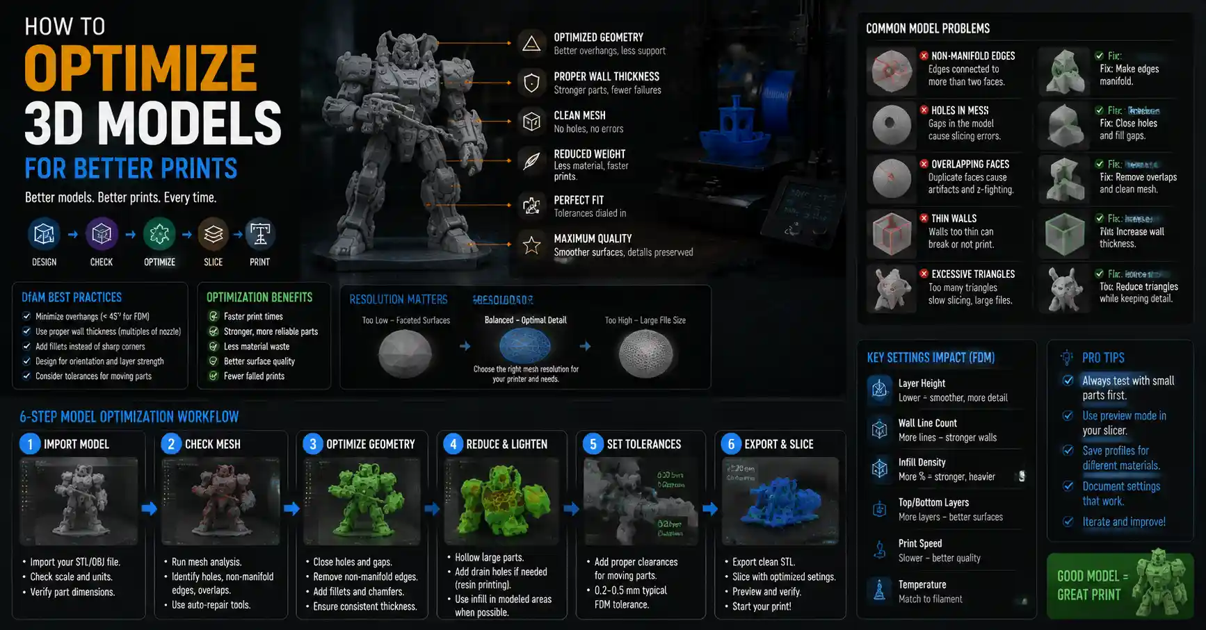
If you’ve ever spent hours calibrating your 3D printer, tweaking temperature settings, and troubleshooting layer adhesion issues only to end up with a warped, lopsided print that doesn’t fit together, the problem might not be your machine. More often than not, poor 3D print quality comes down to an unoptimized 3D model. Even a design that looks perfect in CAD software can hide flaws that turn a 2-hour print into a pile of plastic waste. Optimizing your model before sending it to the slicer cuts down on print time, reduces material waste, improves strength, and delivers consistent, professional results. Whether you’re a hobbyist printing cosplay props, an engineer prototyping a custom part, or a small business selling 3D printed goods, these optimization strategies will help you get more out of every print.
Start with Design for Additive Manufacturing (DfAM) Basics
Optimization begins long before you export an STL file. The core principles of Design for Additive Manufacturing (DfAM) are built around the unique constraints and capabilities of 3D printing, and ignoring them can lead to avoidable problems down the line. Unlike traditional manufacturing methods like CNC milling or injection molding, 3D printing builds parts layer by layer, which creates different rules for geometry, overhangs, and wall strength.
Account for Overhangs and Unsupported Geometry
Nearly all consumer and professional FDM 3D printers require support material for any overhang angled steeper than 45 degrees from the vertical plane resin printers can often handle angles as steep as 20-30 degrees, but still struggle with fully horizontal overhangs. Adding supports means extra material, longer print time, and visible blemishes on the finished part that require sanding to fix. Optimizing your design to eliminate unnecessary overhangs reduces or even eliminates the need for supports entirely.
For example, if you’re designing a bracket with a 90-degree protruding edge, you can tweak the design to add a gradual chamfer that brings the angle below 45 degrees. If the overhang is necessary for function, you can thicken the base of the overhang or add a fillet that transitions the angle more gradually. For interlocking parts, orienting the design to place overhangs along existing axes of the part can also reduce the need for extra support.
Set Minimum Feature Sizes for Your Printer
Every 3D printer has a minimum feature size, determined by the nozzle diameter (for FDM) or laser spot size (for resin SLA/DLP). A common mistake new designers make is adding tiny 0.5mm holes or thin 1mm walls to a model that will be printed with a 0.4mm nozzle. The result is features that either don’t show up at all, or are too fragile to survive removal from the build plate.
A good rule of thumb for FDM printing is to make all wall thicknesses a multiple of your nozzle diameter. For a standard 0.4mm nozzle, that means 1.2mm (three perimeter lines) or 0.8mm (two perimeter lines) for thin walls, rather than an arbitrary 1mm that will leave gaps between perimeters. For resin printers, minimum feature sizes are typically between 0.2mm and 0.5mm, depending on the pixel resolution of your screen. Check your printer’s documentation and set hard minimums in your CAD software to avoid unprintable features.
“The best 3D print optimization is done in CAD, not in Meshmixer or the slicer. Fixing a bad design at the source saves hours of rework later.”
Optimize for Orientation Early
Orientation—the way your part sits on the build plate—affects everything from strength to surface finish to the need for supports. Many designers wait until they get to the slicer to think about orientation, but building orientation into your design can drastically improve outcomes. For example, if you know your part will be oriented with the longest edge vertical, you can adjust wall thicknesses to account for the layer bonding direction. 3D printed parts are always weaker along the Z-axis, so if your part will bear a load, orient the design so the force is applied along the XY plane rather than pulling apart layers.
Pre-Process STL Files to Fix Common Mesh Errors
Most 3D printers rely on the STL file format, which converts your CAD model into a mesh of triangular facets. This format is universal, but it’s also prone to errors that can cause slicing failures, misprinted layers, or rough surfaces. Even a perfect CAD design can develop errors when exported to STL, so pre-processing your mesh is a non-negotiable step in optimization.
Check for Common Mesh Errors
There are four common mesh errors that break 3D prints, and fixing them takes just a few minutes in free software like MeshLab, Meshmixer, or Blender:
- Non-manifold edges: Edges that are shared by more or fewer than two faces, creating gaps or overlapping geometry that slicers can’t interpret.
- Degenerate triangles: Triangles with zero area that create invisible holes or artifacts in the mesh.
- Holes in the mesh: Gaps between faces that leave an open edge, turning a solid model into a hollow shell that slicers can’t fill correctly.
- Overlapping faces: Two or more faces occupying the same space, which can confuse slicers and create extra uneven layers in the print.
Most modern CAD software includes a built-in STL repair tool, and free tools like MeshLab have one-click "make manifold" functions that automatically fix the majority of these errors. For complex models, it’s worth running a manual check after automatic repair to catch any small holes that were missed, especially around intricate features like screw holes or interlocking joints.
Adjust Mesh Resolution for Your Needs
When exporting an STL from CAD, you can choose the resolution of the mesh, which controls how many triangles are used to represent curved surfaces. Too low a resolution, and you’ll get a jagged, faceted print that doesn’t match your original design. Too high a resolution, and you’ll end up with a massive file that slows down your slicer, causes crashes, and adds unnecessary processing time.
The optimal resolution depends on the size of your part and the level of detail you need. A good rule of thumb is to set the maximum deviation half the size of your nozzle diameter. For a 0.4mm nozzle, that means a maximum deviation of 0.2mm. This gives you smooth curves without adding excess triangles. For large parts like cosplay armor, you can use a lower resolution, since small facets won’t be visible at scale. For small intricate parts like jewelry or mechanical components, use a higher resolution to preserve fine details.
Hollowing and Lightweighting Solid Models
Unless your part requires full solid density for strength, hollowing or lightweighting your model is one of the most effective optimizations you can make. It cuts down on print time, reduces material use, and lowers the risk of warping by reducing internal heat buildup in large prints. For resin prints, hollowing also saves expensive resin and reduces the weight of the finished part.
When hollowing a model, make sure to add at least two drain holes if you’re using resin printing—one to let excess resin flow out of the hollow cavity during printing, and another to equalize pressure. For FDM prints, you don’t need drain holes, but you should leave consistent wall thickness that matches your nozzle settings (usually 1.2-2mm for a 0.4mm nozzle). For an even more optimized lightweight part, you can use lattice infill structures designed in CAD, rather than relying on your slicer to generate internal infill. Lattice structures can provide better strength-to-weight ratios than standard infill, especially for large structural parts.
Optimize Models for Strength and Functionality
A common goal for 3D printed parts is to match or exceed the strength of a traditionally manufactured part. Optimization for strength doesn’t just mean turning up the infill percentage in your slicer—it requires intentional design changes to your model that improve performance.
Reinforce High-Stress Areas
3D printed parts almost always fail at stress concentration points: sharp internal corners, notches, or sudden changes in wall thickness. Optimizing these areas can double or triple the part’s lifespan without adding much material or weight.
The simplest fix is to add fillets to all internal corners. A sharp 90-degree internal corner creates a stress riser that can cause a crack to form under even moderate load. Adding a fillet with a radius of at least 1-2mm distributes stress evenly across the corner, drastically improving strength. For parts that will bear heavy loads, you can also add gussets (reinforcing triangular ribs) to joints and protruding features. Gussets add minimal weight but greatly increase stiffness and resistance to bending.
Tune Tolerances for Interlocking Parts
One of the most frustrating 3D printing problems is a functional part where screws don’t fit, or two pieces that are supposed to snap together are either too tight or too loose. Optimizing tolerances— the intentional gap between moving or interlocking parts—solves this issue, and the right tolerance depends on your printer, filament, and printing settings.
For example, if you’re designing a hole for a standard M3 screw, you’ll need to make the hole slightly larger than 3mm to account for elephant’s foot (a slight expansion of the first layer) and over-extrusion. For most FDM printers printing with PLA, a 0.1-0.2mm gap between mating parts works for a slip fit, while a 0.3-0.5mm gap works for a loose moving fit. Resin printers can achieve much tighter tolerances, often as small as 0.05mm for a slip fit.
The best practice is to print a simple tolerance test card (available for free on sites like Thingiverse) for your specific printer and settings, then adjust your model’s tolerances to match. This one small step eliminates 90% of fit issues with functional assemblies.
- Print a tolerance test card specific to your printer type (FDM or resin)
- Measure the actual gap size of each test fit with calipers
- Record the tolerance that gives you the desired fit (slip, press, or moving)
- Apply that tolerance to all mating features in your 3D model
- Test print one interlocking part before printing the full assembly
Compensate for Warping and Shrinkage
Every 3D printing material shrinks as it cools, and some materials like ABS can shrink by as much as 2% overall. If you’re printing a dimensionally accurate part like a replacement gear or a custom bracket for an existing product, you need to compensate for shrinkage in your model before printing.
Most slicers have a built-in linear scaling feature, but scaling your model in CAD is more precise, especially for parts with specific critical dimensions. To find the right scaling factor, print a calibration test cube of 100mm x 100mm x 100mm, measure each dimension with calipers, then calculate the shrinkage percentage. For example, if your 100mm cube comes out at 98.5mm along the X-axis, you’ll need to scale your model by 100/98.5 ≈ 1.5% along that axis to get an accurate final dimension. For large parts, adding a fillet to the base where the part meets the build plate also reduces warping by reducing internal stress as the plastic cools.
Optimize for Print Time, Material Use, and Cost
For anyone 3D printing professionally or producing parts in bulk, reducing print time and material use directly translates to lower costs and higher throughput. Many of these optimizations are simple changes to your model that don’t affect the final part’s performance or strength.
Remove Unnecessary Material
It’s common to carry over design features from traditionally manufactured parts into 3D printed designs that don’t need them. For example, a fully solid 10mm thick boss for a screw hole adds a lot of extra print time and material, when a 2mm thick hollow boss with a reinforced opening is just as strong.
Go through your model and identify any features that don’t serve a functional or aesthetic purpose. Can you reduce the thickness of a non-load-bearing wall? Can you cut out a large section of internal material that will never be seen? Even small reductions add up for large prints or bulk production. For example, removing 10 grams of plastic from a part that you print 100 times saves 1 kilogram of filament, which is worth $20-$50 depending on the material.
Modify Models to Avoid Multi-Part Printing
If your model is too large to fit on your printer’s build plate, you have to split it into multiple parts, print them separately, and glue them together. While splitting is sometimes unavoidable, you can often optimize the model to fit in a single print by rotating or reorienting the design in CAD. A 200mm long part that doesn’t fit along the X-axis may fit diagonally across a 200mm x 200mm build plate, for example, cutting out the time needed to split, print, and assemble multiple pieces.
If you do have to split a large model, add alignment pins and holes to the cut faces in your CAD software. This makes assembly much easier and ensures the parts line up correctly without guessing. Adding these alignment features during the design phase is far more effective than trying to add them after splitting the mesh in a separate tool.
Optify Layout for Batch Printing
If you’re printing multiple models in a single batch, optimizing the layout of the models on the build plate in your modeling software (before you get to the slicer) can reduce print time and improve success rates. Leave at least 5-10mm of space between models to allow elephant’s foot and avoid priming blobs from connecting one model to the next. For small parts, arrange them in a grid that maximizes the number of parts per print without overcrowding. If you’re printing with a tool-changing or multi-material printer, group parts by material to reduce the number of tool changes, which cuts down on total print time.
Optimize Surface Quality Post-Processing Preparation
If you plan to sand, paint, or finish your 3D print after printing, optimizing your model for post-processing can cut down on the time you spend finishing and deliver a better final result.
Add Allowance for Sanding and Machining
If you plan to sand the surface of your print to remove layer lines, add 0.1-0.5mm of extra material to all external surfaces that will be sanded. This extra material gives you room to sand down the layer lines without making the part too small or ruining critical dimensions. For parts that will be machined after 3D printing (for example, a custom aluminum mold 3D printed in PLA for thermoforming), add 1-2mm of extra material to any surface that will be milled or lathed to get the final dimension.
Eliminate Blemishes from Supports in Design
If you can’t avoid supports, design your model to place the support contact points on surfaces that will be hidden or sanded after printing. For example, if you’re printing a figurine with an overhanging arm, place the support on the underside of the arm, where the mark will be hidden when the part is displayed, rather than on the front of the arm where the blemish will be visible. For functional parts, add a small nub to the part where the support will attach. The nub will be cut off and sanded after printing, leaving a clean surface on the main part.
Smooth Curves and Avoid Over-Detailing
3D printing can’t replicate every tiny detail you add to a CAD model, especially with FDM. Adding tiny engravings or surface details smaller than your nozzle diameter will just end up as a blurry mess, and they add extra triangles to your mesh that slow down slicing. Remove any details smaller than your printer’s minimum feature size, and make sure large curved surfaces are properly subdivided to avoid jagged facets that require extra sanding to fix.
Conclusion
Optimizing a 3D model for printing isn’t just a matter of fixing mesh errors or adjusting resolution—it’s a holistic process that starts in CAD and continues through to pre-slicer prep. By following DfAM principles, fixing common mesh errors, optimizing for strength and functionality, reducing material use and print time, and preparing for post-processing, you can turn inconsistent, wasteful prints into consistent, professional results. The best part is that most of these steps take just a few extra minutes before you export your STL, and they save hours of troubleshooting, reprinting, and post-processing down the line. Whether you’re printing one custom part or hundreds of parts for sale, model optimization is the most impactful thing you can do to improve your 3D printing outcomes.